Home > Product > DCS control system > 193X532ADG01 on-site control board

193X532ADG01 on-site control board
- Goods status: new/used
- Delivery date: stock
- The quality assurance period: 365 days
- Phone/WhatsApp/WeChat:+86 15270269218
- Email:stodcdcs@gmail.com
- Tags:
- Get the latest price:Click to consult
193X532ADG01 on-site control board
Product Details Introduction
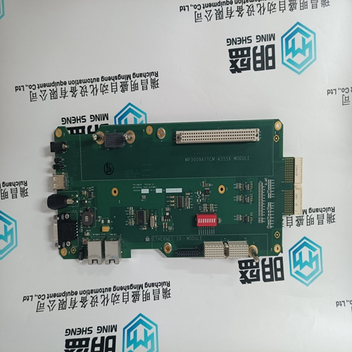
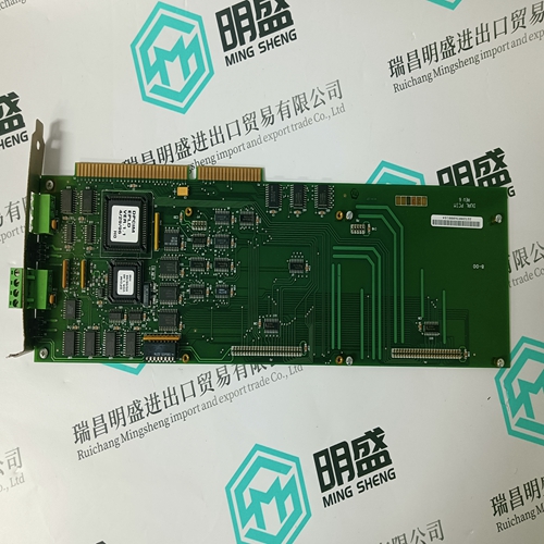
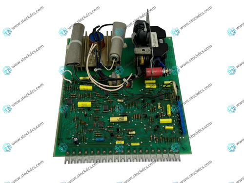
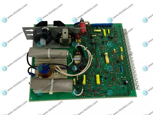
GE 193X532ADG01 is a field control board in General Electric's 193X series, widely used in early GE industrial drive systems, especially in DC and AC drive devices and process control systems, playing a core role in field signal processing and control instruction execution. This board is usually installed in the control rack or control cabinet and operates in conjunction with other functional modules within the system.
Technical specifications and functional features
Control type: mainly analog signal control, supplemented by some digital logic functions
Input signals: standard industrial analog signals (such as 0-10V, 4-20mA), digital contacts
Output signals: control voltage/current, switch signal, logic control signal
Working voltage: generally ± 15V DC (system power supply)
Adjustment function: onboard multi turn potentiometer, used to adjust parameters such as gain, zero point, response, etc
Circuit composition: Using discrete electronic components (operational amplifiers, transistors, capacitors, resistors, etc.) to construct stable control logic
Interface form: Card type gold finger design, connected to the back panel of GE control chassis
Status indicator: Some versions come with status LED lights for debugging and running instructions
Application scope
GE Early Mark Series Drive Control System
DC/AC motor speed control system
Motor control in metallurgical industry
Power plant excitation control system
Control of actuators in continuous control processes such as chemical, papermaking, and energy industries
Installation and usage precautions
Ensure that the system is completely powered off before installation, and avoid electric shock or damage to the interface during the plugging and unplugging process.
Pay attention to anti-static treatment during use to prevent static discharge from damaging circuit components.
Before use, carefully check whether the wiring definition, input and output signal types of the board are consistent with the system requirements.
It is recommended to regularly (every 6-12 months) inspect the control board, including issues such as capacitor aging, solder joint virtual soldering, and poor contact.
During the debugging process, oscilloscopes and multimeters can be used to measure the waveform or voltage values of key point signals to determine if the circuit is functioning properly.
Product imag
Related website links
ABB SB822 3BSE018172R1 rechargeable
CI860K01 3BSE032444R1 power module
Other website links
KOLLMORGEN CP310250 PRD-P310250Z-55 伺服驱动器
| PMA45R-00100-00 | AMAT 0100-00127 | PFTL 101A-0.5 |
| PMA45Q-10100-00 | AMAT 0100-00177 | PFRL101A 0.5KN |
| PMA45N-01100-00 | AMAT 0100-35263 | PFRL101D |
| PMA45N-00100-00 | AMAT 0100-09302 | PFTL 101AE-0.5 |
| PMA44R-1050B-08 | AMAT 0100-00055 | PFTL 101BER-20.0KN |
| PMA44R-10100-00 | AMAT 0100-A1201 | PFTL 201DE-100.0KN |
| PMA44R-00100-00 | AMAT 0100-35069 | PFTL 201CE-10.0KN |
| PMA44P-00100-00 | AMAT 0100-35213 | PFTL 101AER-2.0KN |
| PMA44N-01100-00 | AMAT 0100-14003 | PFTL 301E-0.2 |