Home > Product > PLC programmable module > 1756-EN2T/B industrial module
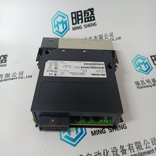
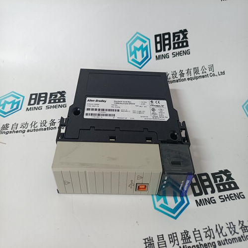
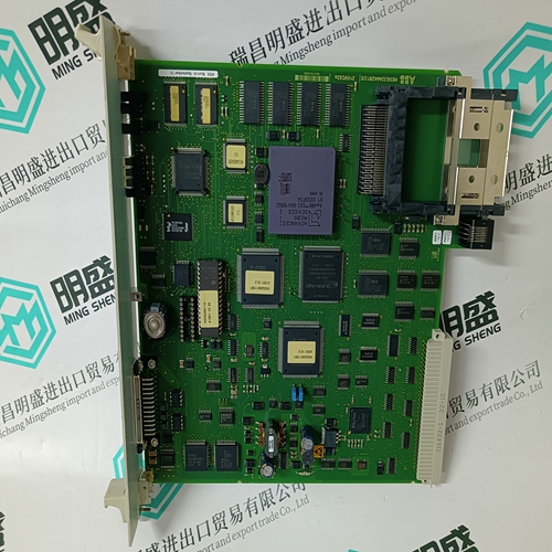
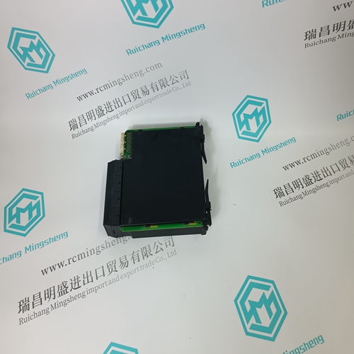
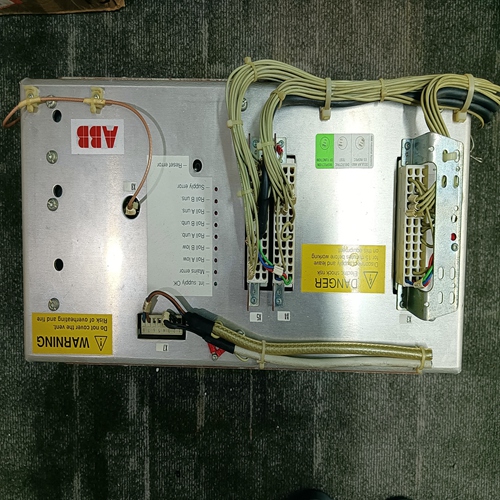
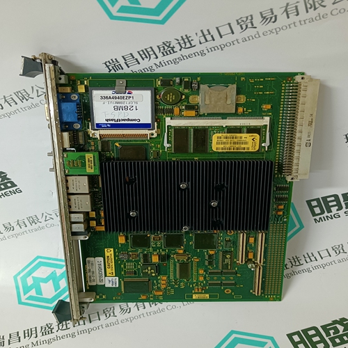
1756-EN2T/B industrial module
- Product ID: 1756-EN2T/B
- Brand: A-B
- Place of origin: the United States
- Goods status: new/used
- Delivery date: stock
- The quality assurance period: 365 days
- Phone/WhatsApp/WeChat:+86 15270269218
- Email:stodcdcs@gmail.com
- Tags:1756-EN2T/Bindustrial module
- Get the latest price:Click to consult
The main products
Spare parts spare parts, the DCS control system of PLC system and the robot system spare parts,Brand advantage: Allen Bradley, BentlyNevada, ABB, Emerson Ovation, Honeywell DCS, Rockwell ICS Triplex, FOXBORO, Schneider PLC, GE Fanuc, Motorola, HIMA, TRICONEX, Prosoft etc. Various kinds of imported industrial parts
Products are widely used in metallurgy, petroleum, glass, aluminum manufacturing, petrochemical industry, coal mine, papermaking, printing, textile printing and dyeing, machinery, electronics, automobile manufacturing, tobacco, plastics machinery, electric power, water conservancy, water treatment/environmental protection, municipal engineering, boiler heating, energy, power transmission and distribution and so on.

1756-EN2T/B industrial module
In order to avoid faults and disturbances at the other loads, that are connected to the secondary side of the matching transformer, the sum of the system fault level (short–circuit power) of the plant connection and that of the matching transformer at the connection point (SK line supply) must contain at least the values shown in Table 7-1, Chapter LEERER MERKER. Depending on the vector group of the transformers, e.g. YYn0, asymmetric loading of the N/MP may not be permitted. Consequently, the required rated power Sn2 of the
The system fault level at the plant connection SK plant plays a decisive role in dimensioning/selecting the matching transformer. From the rated power (Sn1 or Sn2) calculated under a) and b), the higher must be used for the matching transformer.
Assignment of the line fuses to the NE modules
Fuses or circuit breakers are necessary to protect the cables against short–circuit/ground fault, to limit any damage to the converter, provide protection against electric shock and to avoid fire in the case of a fault. The overvoltage protective devices must be located before the terminals of the drive lineup (line filter or HFD reactor)! ! Danger Overvoltage protective devices only on the primary side of a transformer, which may be possibly used, are not sufficient to protect the converter or protect against fire! Fuses and plant conditions, such as loop resistance and short–circuit power, must be harmonized with each other so that the limit curve shown in Fig. 7-8 is not exceeded. Circuit breakers (Table 7-6) or alternatively, fuses (Table 7-7) should be used. The appropriate protection measure should be selected corresponding to the local situation from Table 7-5.
The calculated maximum short–circuit current
at the connection point is an important indicator for dimensioning the required switching capacity of protective elements, fuses/circuit breakers. Protection elements should be dimensioned so that the maximum permissible short–circuit current can be reliably switched by the selected protection element. The calculated minimum short–circuit current at the connection point is an important indicator for the maximum permissible tripping time of protection elements, fuses/circuit breakers. Protection elements should be dimensioned so that at the minimum short–circuit current expected, these still reliably trip within the maximum permissible trip time specified by the device manufacturer in order to guarantee protection for personnel and avoid the risk of fire. When connecting the machine, using a suitable measuring device (according to DIN, EN, IEC 61557–3; VDE 0413–3) at the connection point of the drive system, the short–circuit current should be determined and the overcurrent protective devices installed checked to ensure that they comply with these operating conditions. The measuring results and installed protection elements must be documented so that they can be subsequently verified when required.