Home > Product > PLC programmable module > 1756-L61/B processor module
1756-L61/B processor module
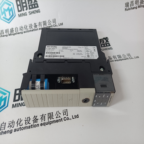
- Product ID: 1756-L61/B
- Brand: A-B
- Place of origin: the United States
- Goods status: new/used
- Delivery date: stock
- The quality assurance period: 365 days
- Phone/WhatsApp/WeChat:+86 15270269218
- Email:stodcdcs@gmail.com
- Tags:1756-L61/Bprocessor module
- Get the latest price:Click to consult
The main products
Spare parts spare parts, the DCS control system of PLC system and the robot system spare parts,Brand advantage: Allen Bradley, BentlyNevada, ABB, Emerson Ovation, Honeywell DCS, Rockwell ICS Triplex, FOXBORO, Schneider PLC, GE Fanuc, Motorola, HIMA, TRICONEX, Prosoft etc. Various kinds of imported industrial parts
Products are widely used in metallurgy, petroleum, glass, aluminum manufacturing, petrochemical industry, coal mine, papermaking, printing, textile printing and dyeing, machinery, electronics, automobile manufacturing, tobacco, plastics machinery, electric power, water conservancy, water treatment/environmental protection, municipal engineering, boiler heating, energy, power transmission and distribution and so on.

1756-L61/B processor module
For trial operation when connected to line supplies that do not have adequate short–circuit power (system default level), the protection elements should be adapted so that they trip within approx. 10 ms in the case of a fault, as otherwise there is a risk of significant damage to the device or fire. It is not permissible to overdimension the protection elements. Note The recommended circuit breakers are sufficient for a maximum short–circuit current (SCCR) < 65 kA of the drive lineup. For line supplies that deviate from this with a smaller or higher line short–circuit power, these can or must be appropriately re–dimensioned.For timely tripping of fuses, the loop resistance as well as the vector group of the line supply transformer being fed must satisfy the requirement that the touch voltage of the devices is switched off by the provided fuses within the permissible tripping time (see Fig. 7-8 in accordance with EN 61800–5–1 Ed. 2007)
Assigning the main switches
The main switches must be chosen appropriately for the machine (scope of the installation), the supply line characteristics (voltage, short–circuit power), regional regulations for plant/machine constructors. Recommendation: Siemens 3LD.../3KA... switch types (as listed in the SIEMENS ”Low–Voltage Switchgear” catalog)For various plant and system configurations the use and the correct connection of a leading contact (integrating terminal 48) for the switching element is either absolutely necessary or not required. In this connection, switching elements are: Power disconnectors (mains switch, line supply contactor) Note During the shutdown, to prevent damaging overvoltages that can damage parallel–operated loads, terminal 48 of the NE modules must be switched off 10 ms before deenergizing the line supply contacts. Main switches (breakers) with leading auxiliary contact can be used to ensure that terminal 48 of the NE modules is deenergized using a leading contact. Leading shutdown is not required for certain drive configurations. For information refer to Section 7.3.6.
If the objective is that an application
is not to have a leading contact over the complete power range of the infeed modules, then this can be implemented using the following measures: Changing over from any present I/R modules to unregulated infeed (this is generally the case for 480 V applications). Deactivating the regenerative feedback if I/R modules are being used. The I/R modules then operate as UI modules and can be operated with additional loads connected to a switching element without leading contact. For the configurations that are now described, a leading contact for the switching element is absolutely necessary: If one or more I/R modules are connected, together with other loads, through a switching element. If NE modules having different power classes are connected together to one switching element. In this case, the restrictions, described on the following page, must be carefully fulfilled. The following diagram shows two examples where a leading contact is absolutely necessary