Home > Product > DCS control system > SCYC51040 58052680E Interface component module
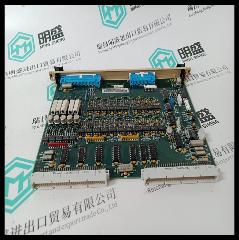
SCYC51040 58052680E Interface component module
- Product ID: SCYC51040 58052680E
- Brand: ABB
- Place of origin: The Swiss
- Goods status: new/used
- Delivery date: stock
- The quality assurance period: 365 days
- Phone/WhatsApp/WeChat:+86 15270269218
- Email:stodcdcs@gmail.com
- Tags:SCYC51040 58052680EInterface component module
- Get the latest price:Click to consult
The main products
Spare parts spare parts, the DCS control system of PLC system and the robot system spare parts,
Brand advantage: Allen Bradley, BentlyNevada, ABB, Emerson Ovation, Honeywell DCS, Rockwell ICS Triplex, FOXBORO, Schneider PLC, GE Fanuc, Motorola, HIMA, TRICONEX, Prosoft etc. Various kinds of imported industrial parts
Products are widely used in metallurgy, petroleum, glass, aluminum manufacturing, petrochemical industry, coal mine, papermaking, printing, textile printing and dyeing, machinery, electronics, automobile manufacturing, tobacco, plastics machinery, electric power, water conservancy, water treatment/environmental protection, municipal engineering, boiler heating, energy, power transmission and distribution and so on.
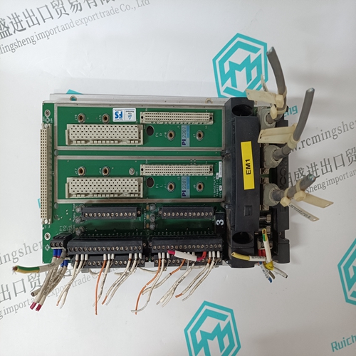
SCYC51040 58052680E Interface component module
The comprehensive description for this central unit is located in volume 5. Brief description The central unit CS 20 works as a ● Stand-alone central unit. Main features : ● Power supply 24 VDC or 120 VAC or 230 VAC (3 versions) ● 12 binary inputs (one of them is a high-speed input) ● 8 binary relay outputs ● 1 integrated high-speed counter ● Serial interface COM1, EIA-232, for programming ● Real-time clock ● LEDs for displaying of the input and output signals as well as error messages and the RUN operating condition. ● Fastening by inserting in the plug-in base ECZ. The plug-in base can either be snapped on a DIN rail or fastened by screws. ● Built-in lithium battery for back-up of the RAM contents, its lifetime is 10 years. ● RUN/STOP switch for starting and aborting the program execution. ● Diagnosis functions. ● Programming with the programming software : 907 PC 29 ● User program containing max. 2 k instructions.
The central units 07 KR 31
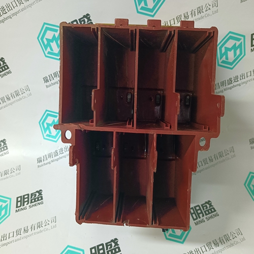
PCZB/CS20 and all of the remote units must be mounted on a plug-in base ECZ, with screw termination. The plug-in base is suitable for rail mounting : (35 mm EN 50 022). It consist of : ● 30 screw terminals for the connecting cables ..........➀ ● 8 dip switches to set the address of the unit............➁ ● 2 holes to allow screw fixing ...................................... ➂ ● One 96 way connector for connection to the plug-in unit ➃ ● 1 voltage selector 24 VDC, 120 and 230 VAC ........➄ ● Rail fixing................................................................. ➅ The following terminals are : ● Terminal 1 : bus 2 ● Terminal 2 : bus 1 ● Terminal 3 : shield of bus ● Terminal 16 : power supply 24 VDC or 120 VAC or 230 VAC ● Terminal 17 : power supply 0 VDC or 120 VAC or 230 VAC ● Terminal 18 : functional earth ● Termination – on the plug-in base ECZ use 60 °C copper conductor only Cross section : – bus wiring terminal : twisted pair AWG 24 (0.22 mm2 ) to AWG 18 (0.8 mm2 ) – earth terminal : rigid or stranded connector AWG 10 (5.2 mm2 ) – Others terminals : ● inputs : stranded connector AWG 18 (0.8 mm2) to AWG 14 (2.1 mm2 ) ● outputs : stranded connector AWG 14 (2.1 mm2 ) ● power supply AWG 14 (2.1 mm2 ) Screws thightening torque (for guidance only) 7 Lbs. in (0.8 N.m). An LC filter is built into the base
Electrical connection
The common "+" terminals are connected together. Power supply 24 VDC The common "+" must not be used.Note : In case of use of an external power supply 24 VDC for inputs, the "0" VDC has to be connected to the common "–". Caution : The 24 VDC must never be connected to common "+". ● Initialization After configured and wired the unit : – the unit initializes itself after power On. – the error led goes out after initialization. – the status of 8 inputs is displayed on the 8 led's.
For the PC board 07 CM 90 and the coupler boards 07 CS 61 and 35 CS 91, refer to their own description The available configuration for each input : – delay – open circuit detection ● Fault indication The led's indicate the following : Led 0 : "Unit error" Led 1 : "Bus error" Led 3 : "Cut wire" The status of an input channel is shown by : Led 7 : "Input" If an error occurs the red led error is On (see Chapter 9, Volume 2 «In case of failure»)