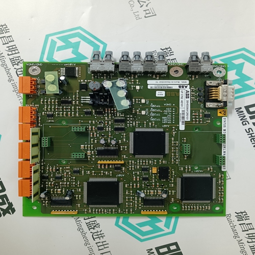
Home > Product > PLC programmable module > ICS TRIPLEX T9100@G2 base module
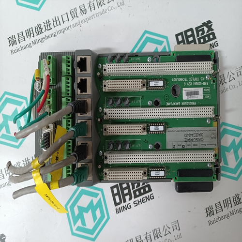
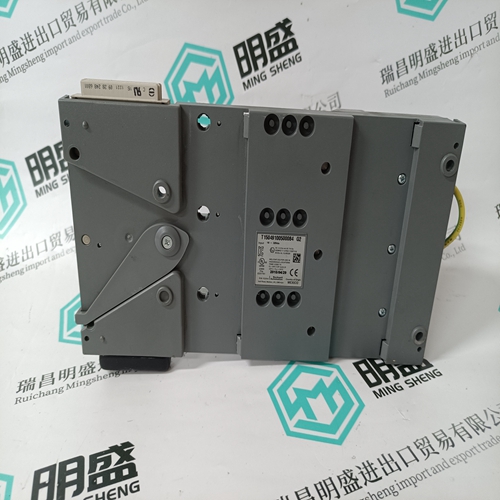
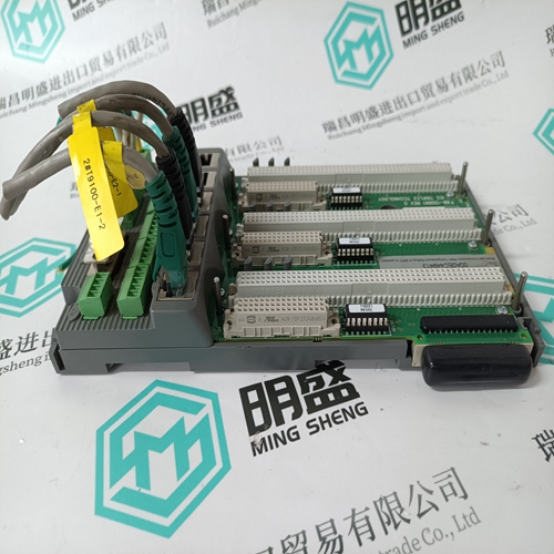
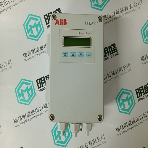
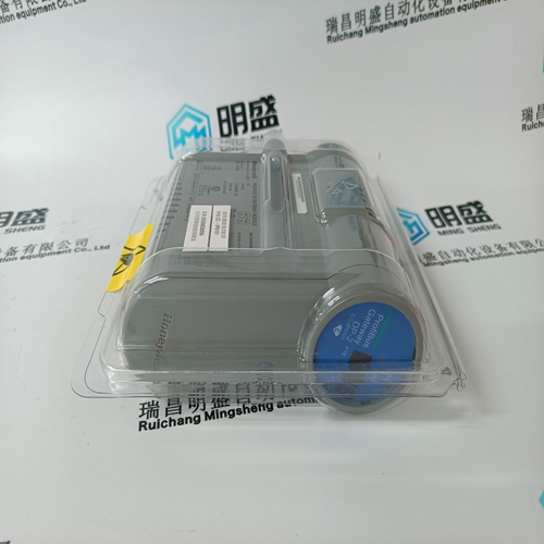
ICS TRIPLEX T9100@G2 base module
- Product ID: T9100@G2
- Brand: ICS TRIPLEX
- Place of origin: the United States
- Goods status: new/used
- Delivery date: stock
- The quality assurance period: 365 days
- Phone/WhatsApp/WeChat:+86 15270269218
- Email:stodcdcs@gmail.com
- Tags:ICS TRIPLEXT9100@G2base module
- Get the latest price:Click to consult
The main products
Spare parts spare parts, the DCS control system of PLC system and the robot system spare parts,
Brand advantage: Allen Bradley, BentlyNevada, ABB, Emerson Ovation, Honeywell DCS, Rockwell ICS Triplex, FOXBORO, Schneider PLC, GE Fanuc, Motorola, HIMA, TRICONEX, Prosoft etc. Various kinds of imported industrial parts
Products are widely used in metallurgy, petroleum, glass, aluminum manufacturing, petrochemical industry, coal mine, papermaking, printing, textile printing and dyeing, machinery, electronics, automobile manufacturing, tobacco, plastics machinery, electric power, water conservancy, water treatment/environmental protection, municipal engineering, boiler heating, energy, power transmission and distribution and so on.
ICS TRIPLEX T9100@G2 base module
INICI12 interface repair is limited to assembly replacement. If a module or termination unit fails, remove and replace it with another. Do not attempt to replace discrete components in any Harmony device. Replacement The replacement procedures for most parts and assemblies are intuitive. Figure 7-1 is the INICI12 interface replacement flowchart, which contains replacement procedures for those parts and assemblies that need explanation. In the flowchart, each flowchart block represents a single task. The PR code in the flowchart block identifies the procedure section that describes the steps to complete the indicated task. Some steps are self-explanatory and have no related procedure section. Complete all steps given in a procedure section before continuing to the next flowchart block. The procedure sections are located towards the back of the instruction.
Order parts without commercial descriptions from the nearest ABB sales office. Contact ABB Automation for help determining the quantity of spare parts to keep on hand for your particular system. Tables 8-1 through 8-3 list INICI12 interface related parts.
Purpose/Scope
This procedure describes the steps required to properly set up the IEMMU11, IEMMU12, EMMU21, or IEMMU22 Module Mounting Unit for the INICI12 interface.Procedure □ 1. Verify the MMU slot assignments for the INNIS01 and INICT12 modules. □ 2. From the front of the module mounting unit insert a 24-pin dipshunt with all pins intact in the I/O expander bus socket (XU1 to XU11) between the MMU slot to be used by the INNIS01 module and the slot to be used by the INICT12 module. □ 3. Remove any 24-pin dipshunts from the I/O expander bus sockets that would connect the INNIS01 and INICT12 modules to any other modules.This procedure gives the steps required to connect a host computer to the RS-232-C port of the NTMP01 termination unit. Parts • RS-232-C cable with a DB-25 connector. Tools None. The RS-232-C port zero (P5) and port one (P6) are standard DB-25 connectors. Normally, port zero is used for host computer connection and port one is used for diagnostic terminal or security key connection. The host computer can either connect directly to the NTMP01 unit or connect through a modem. The RS-232-C ports on the NTMP01 unit are isolated. NOTE: The INICI12 interface supports only one host computer connection. Procedure □ 1. Connect the DB-25 end of the RS-232-C cable to port zero (P5) of the NTMP01 unit (Fig. PR11-1). Table PR11-1 shows the P5 and P6 connector pin assignments. □ 2. Connect the other end of the RS-232-C cable to the external serial device (i.e., host computer or modem).
