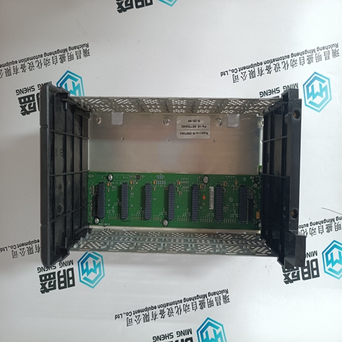
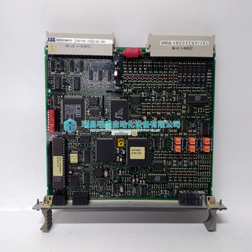
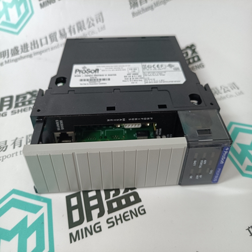
Home > Product > DCS control system > 5X00226G01 Channel interface module
5X00226G01 Channel interface module
- Product ID: 5X00226G01
- Brand: EMERSON
- Place of origin: The United States
- Goods status: new/used
- Delivery date: stock
- The quality assurance period: 365 days
- Phone/WhatsApp/WeChat:+86 15270269218
- Email:stodcdcs@gmail.com
- Tags:5X00226G01Channel interface module
- Get the latest price:Click to consult
The main products
Spare parts spare parts, the DCS control system of PLC system and the robot system spare parts,Brand advantage: Allen Bradley, BentlyNevada, ABB, Emerson Ovation, Honeywell DCS, Rockwell ICS Triplex, FOXBORO, Schneider PLC, GE Fanuc, Motorola, HIMA, TRICONEX, Prosoft etc. Various kinds of imported industrial parts
Products are widely used in metallurgy, petroleum, glass, aluminum manufacturing, petrochemical industry, coal mine, papermaking, printing, textile printing and dyeing, machinery, electronics, automobile manufacturing, tobacco, plastics machinery, electric power, water conservancy, water treatment/environmental protection, municipal engineering, boiler heating, energy, power transmission and distribution and so on.

5X00226G01 Channel interface module
Braking using terminal 64 – drive inhibit – at the current limit By inhibiting terminal 64 – drive enable at the NE module or the monitoring module – the drives are stopped as quickly as possible at the selected current limit (torque limit)/ramp of the drive module. NE module regenerative feedback power The power rating of the NE module is selected according to the rated power of the connected motors – reduced by a demand factor. When braking at the current limit, ensure that the braking power does not exceed the peak regenerative feedback power of the I/R modules (see Table 6.3) and the braking power of the pulsed resistors in the UI modules. In borderline cases, the NE modules should be dimensioned somewhat larger or additional pulsed resistor modules with external pulsed resistors should be used. Setpoint and actual position value interfaces A complete drive module with power and control module with High Performance for 1FK6 motors is shown in a block diagram in Section 8.4.1. The setpoint is controlled via terminal X141. In circuit example = 1, the setpoint and actual position value interfaces of the NC control, e.g. 840D, are only shown once as a schematic sketch. These are not discussed any further in the additional circuits. A detailed description of the control units is provided in Chapter 5
Definition of the terminology
”Powering–down in an emergency” EMERGENCY OFF and ”Stopping in an emergency” EMERGENCY STOP Actions taken when an emergency arises according to EN 60204–1 (VDE 0113, Part 1): 1998–11, Section 9.2.5.4 should be interpreted as follows: Powering–down in an emergency: In Stop Category 0 according to EN 60204–1; 9.2.2 stopping is achieved by immediately disconnecting the power feed to the machine drive elements (i.e. uncontrolled stop). Generally, this type of power–down operation is interpreted as EMERGENCY OFF. Stopping in an emergency: In stop Category 1 according to EN 60204–1; 9.2.2, a system is stopped in a controlled way; in this case, the power feed to the machine drive elements is maintained in order to stop in a controlled fashion. The power feed is only interrupted when standstill has been reached. Generally, this type of stopping is defined as EMERGENCY STOP. In the circuit examples, when stopping in an emergency, the term EMERGENCY STOP function is used. The EMERGENCY STOP buttons cause a shutdown according to Control Category 3 in compliance with EN 954–1 through two channels using the 3TK2806–0BB4/3TK2842–1BB42 safety relays. When required, the switching devices also allow an EMERGENCY STOP button to be connected in a configuration that is cross–fault circuit proof, Category 4 according to EN 954–1.
Motor holding brake
The holding brake must be controlled in a coordinated way with respect to time. For instance, using the PLC logic as a function of the pulse cancellation, controller enable and speed setpoint input. In this case, the times required for the holding brake to open and close must be taken into account. If the brake control is not optimally harmonized and coordinated, then this results in increased wear and premature loss of the braking performance.
In the circuit examples, for a drive stop, the holding brake is disconnected with drop–out delay using the appropriate hardware in addition to the PLC control. This means that a PLC fault cannot result in the brake being incorrectly controlled when the drive is stationary. It must be decided, on an application–for–application basis, whether when stopping in emergency, the brake is to be shutdown instantaneously or with a delay. Using an internal sequence control, 611U controls allow a holding brake to be controlled in a coordinated way (refer to the Function Description for SIMODRIVE 611 universal). Holding brakes must be provided with external circuitry to dampen overvoltages. For detailed description, refer to the Configuration Manual for SIMODRIVE motors. Safe standstill After the drives have stopped, by safely disconnecting the power feed to the motors, the drives are in the safe standstill condition. When the start inhibit is activated, then the pulses are safely cancelled in the drive modules.