Home > Product > DCS control system > PPD512A10-150000 controller
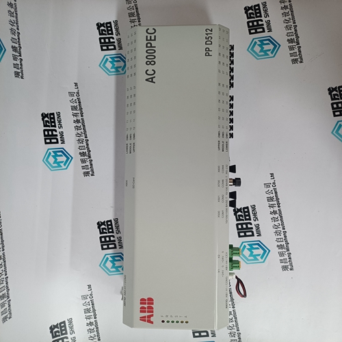
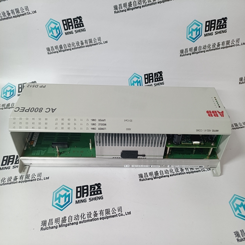
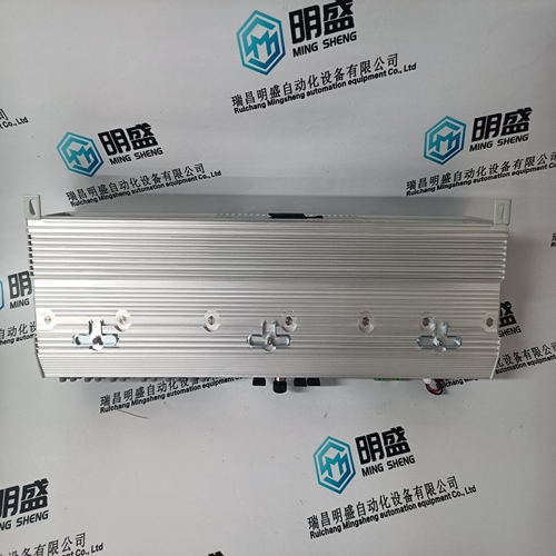
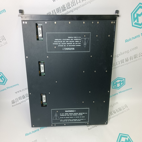
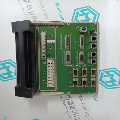
PPD512A10-150000 controller
- Product ID: PPD512A10-150000
- Brand: ABB
- Place of origin: The Swiss
- Goods status: new/used
- Delivery date: stock
- The quality assurance period: 365 days
- Phone/WhatsApp/WeChat:+86 15270269218
- Email:stodcdcs@gmail.com
- Tags:PPD512A10-150000controller
- Get the latest price:Click to consult
The main products
Spare parts spare parts, the DCS control system of PLC system and the robot system spare parts,
Brand advantage: Allen Bradley, BentlyNevada, ABB, Emerson Ovation, Honeywell DCS, Rockwell ICS Triplex, FOXBORO, Schneider PLC, GE Fanuc, Motorola, HIMA, TRICONEX, Prosoft etc. Various kinds of imported industrial parts
Products are widely used in metallurgy, petroleum, glass, aluminum manufacturing, petrochemical industry, coal mine, papermaking, printing, textile printing and dyeing, machinery, electronics, automobile manufacturing, tobacco, plastics machinery, electric power, water conservancy, water treatment/environmental protection, municipal engineering, boiler heating, energy, power transmission and distribution and so on.
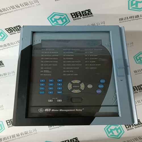
PPD512A10-150000 controller
The Test Output Relay feature provides a method of performing checks on all relay contact outputs. The feature can also be used for control purposes while the motor is running. The forced state overrides the normal operation of the relay output. The forced state, if enabled (energized or de-energized), forces the selected relay into the programmed state for as long as the programmed duration. After the programmed duration expires, the forced state will return to disabled and relay operation will return to normal. If the duration is programmed as Static, the forced state will remain in effect until changed or disabled. If control power to the 369 is interrupted, any forced relay condition will be removed.In addition to the simulation modes, the Test Analog Output setpoints may be used during startup or testing to verify that the analog outputs are functioning correctly. It may also be used when the motor is running to give manual or communication control of an analog output. Forcing an analog output overrides its normal functionality. When the Force Analog Outputs Function is enabled, the output will reflect the forced value as a percentage of the range 4 to 20 mA, 0 to 20 mA, or 0 to 1 mA. Selecting Off will place the analog output channels back in service, reflecting the parameters programmed to each

Immediately prior to a trip
the 369 takes a snapshot of the metered parameters along with the cause of trip and the date and time and stores this as pre-trip values. This allows for ease of troubleshooting when a trip occurs. Instantaneous trips on starting (< 50 ms) may not allow all values to be captured. These values are overwritten when the next trip occurs. The event record shows details of the last 40 events including trips.Any active trips or alarms may be viewed here. If there is more than one active trip or alarm, using the Line Up and Down keys will cycle through all the active alarm messages. If the [LINE UP] and [LINE DOWN] keys are not pressed, the active messages will automatically cycle. The current level causing the alarm is displayed along with the alarm name.
OVERLOAD LOCKOUT TIMER: Determined from the thermal model, this is the remaining amount of time left before the thermal capacity available will be sufficient to allow another start and the start inhibit will be removed. SELECT INHIBIT TIMER: If enabled this timer will indicate the remaining time for the Thermal Capacity to reduce to a level to allow for a safe start according to the Start Inhibit setpoints.
STARTS/HOUR TIMER
If enabled this display will indicate the number of starts within the last hour by showing the time remaining in each. The oldest start will be on the left. Once the time of one start reaches 0, it is no longer considered a start within the hour and is removed from the display and any remaining starts are shifted over to the left. TIME BETWEEN STARTS TIMER: If enabled this timer will indicate the remaining time from the last start before the start inhibit will be removed and another start may be attempted. This time is measure from the beginning of the last motor start. RESTART BLOCK TIMER: If enabled this display will reflect the amount of time since the last motor stop before the start block will be removed and another start may be attempted.
The temperature level of all 12 remote RTDs will be displayed here if programmed and connected to a RRTD module. The name of each RRTD (if changed from the default) will appear as the first line of each message. If option R has not been installed, the following message will appear when attempting to enter this section.